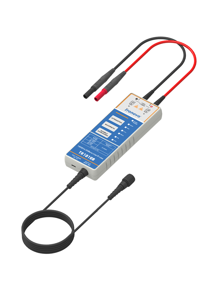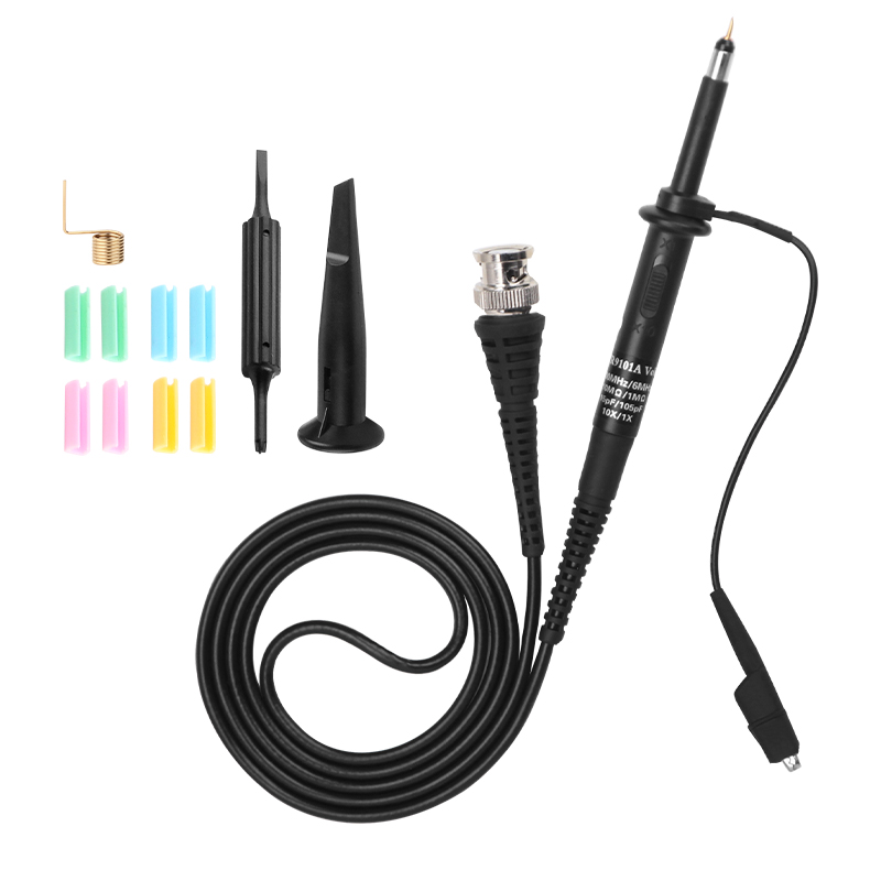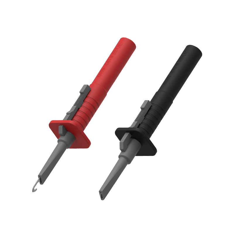

Passive probe as a common oscilloscope accessories, usually in the purchase of oscilloscope will be several standard manufacturers. These passive probes consist of a probe head, a probe cable, a compensation device or other signal conditioning network, and a probe connector. They do not use active components, such as transistors or amplifiers, so there is no need for additional power supply, which is more easy-to-use and cost-effective.
Passive voltage probes provide a variety of attenuation coefficient options for different voltage ranges, of which 10 × passive voltage probes are the most commonly used probes due to their wide applicability. For application scenarios where the signal amplitude is 1V peak-to-peak or lower, a 1x probe may be more appropriate. In applications where low-amplitude and medium-amplitude signals are mixed (e. g., tens of millivolts to tens of volts), a 1 ×/10 × probe that can be switched provides greater convenience. However, it is worth noting that this type of switchable probe is essentially equivalent to two probes with different characteristics integrated into one probe, and their attenuation coefficient, bandwidth, rise time and impedance (R and C) are different. As a result, these probes may not be perfectly matched to the input of the oscilloscope to achieve the optimal performance provided by standard 10x probes.
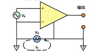
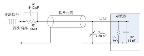
The attenuation function of the passive probe is realized by the internal resistor, which extends the voltage measurement range of the oscilloscope 1 the design. When the internal resistor is used in conjunction with the input resistor of the oscilloscope, a voltage divider is formed. Take a typical 10x probe with a 9MΩ resistor inside. When this probe is connected to an oscilloscope with a 1 MΩ input impedance, a 10:1 attenuation ratio is produced on the oscilloscope's input channels. This means that the signal amplitude displayed on the oscilloscope will be one tenth of the actual measured signal amplitude. Therefore, when using this type of probe, we also need to adjust the attenuation ratio to the corresponding value (such as 10X) in the channel settings of the oscilloscope to ensure the accuracy of the measurement results.

In addition, the attenuation function not only allows us to measure signals beyond the voltage limit of the oscilloscope, but also brings other advantages. The attenuation circuit will result in a higher resistance (which is usually beneficial) and a lower capacitance, which is especially important for the measurement of high-frequency signals. Higher resistance helps reduce current flow, thereby reducing noise and interference; while lower capacitance helps improve signal response speed and measurement accuracy


Building 9, No. 269, Xinfeng Road, Xukou Town, Wuzhong District, Suzhou, China
0512-66559708

WeChat customer

Tmall Official Flagship Store
Copyright © 2003-2025 , All Rights Reserved AiYong Instruments (Suzhou) Co., Ltd.