
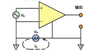
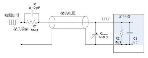
Fundamentally, an oscilloscope is the 1 instrument that measures voltage (on the Y-axis) versus time (on the X-axis), and all voltage measurements are made between two points. When designing an oscilloscope, most designers expect one of these two points to be firmly grounded. Therefore, the probe reference lead of the oscilloscope is electrically connected to the housing of the BNC input, which in turn is connected to the chassis, and finally to ground through the power lead.
However, this design introduces a problem that oscilloscope users often encounter: many voltage measurements are not referenced to ground. Differential voltage and floating voltage are ubiquitous in practical applications, which brings a lot of trouble to users.
When the voltage is not directly referenced to ground, we call it a "floating voltage". Similarly, when a voltage is measured between two points, neither of which is grounded, we call it a "differential voltage". In addition, the signal is usually transmitted differentially through two lines, and the signal transmitted by one line is opposite to the other line. This design can make the receiver effectively suppress any common mode noise.
For example, the differential signal of the CAN bus is the difference between the CAN high level and the CAN low level. This differential transmission method can well suppress common mode noise. In addition, switched-mode power supplies, three-phase power supplies, current-sense resistors, and bio-signals can all suffer from floating or differential signals. If a ground lead is erroneously introduced in such a signal measurement, the light one may cause signal distortion, and the heavy one may even damage the device under test.
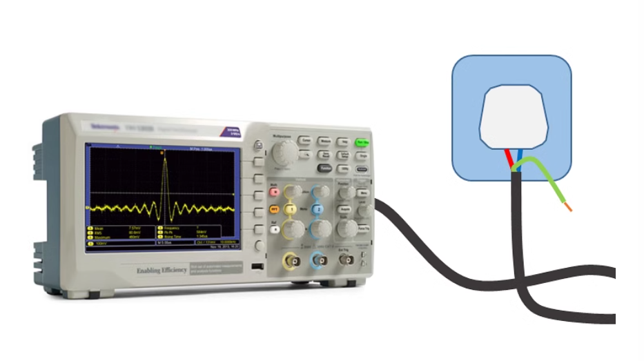
There are several possible solutions to the problem of floating measurements. However, it is not advisable to directly disconnect the ground wire at the power plug, because this will cause the chassis and all BNC inputs to lose ground protection, increasing the risk of electric shock.
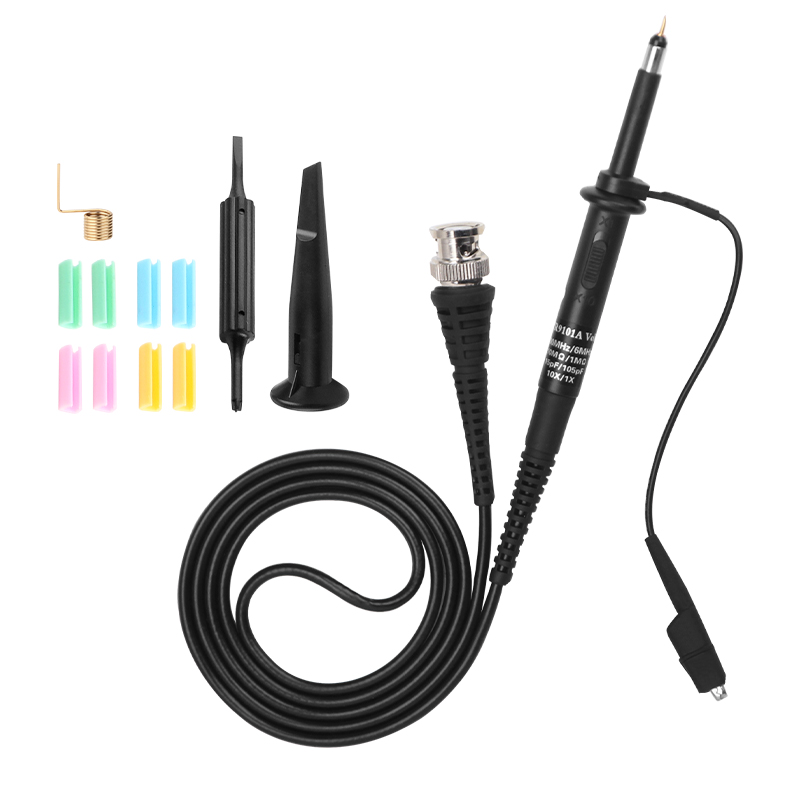
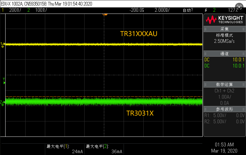
A 1 safer and commonly used method is to use two probes for pseudo-differential measurements. Specifically, two probes are used to measure two points respectively, and then the signal of one channel is inverted, and the signal of the other channel is subtracted from one channel by mathematical methods. In this way, we can only display the differential signal while ensuring the safety of the measurement. However, there are some limitations to this approach, such as the need for two channels and one digital channel to produce one trace, and any imbalance between the probes can result in skew and low common mode rejection ratio (CMRR) between the channels.
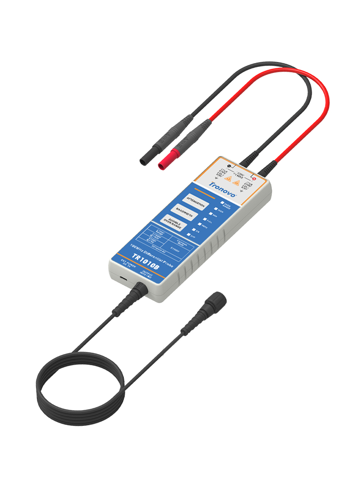
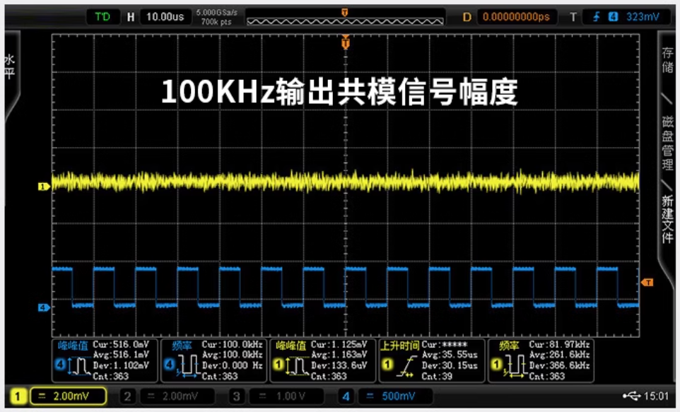
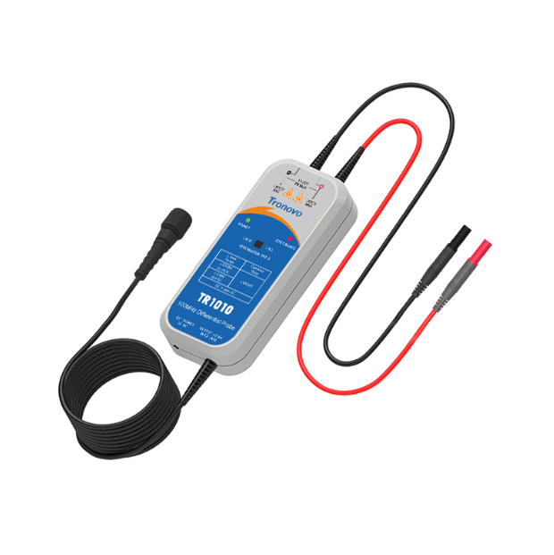
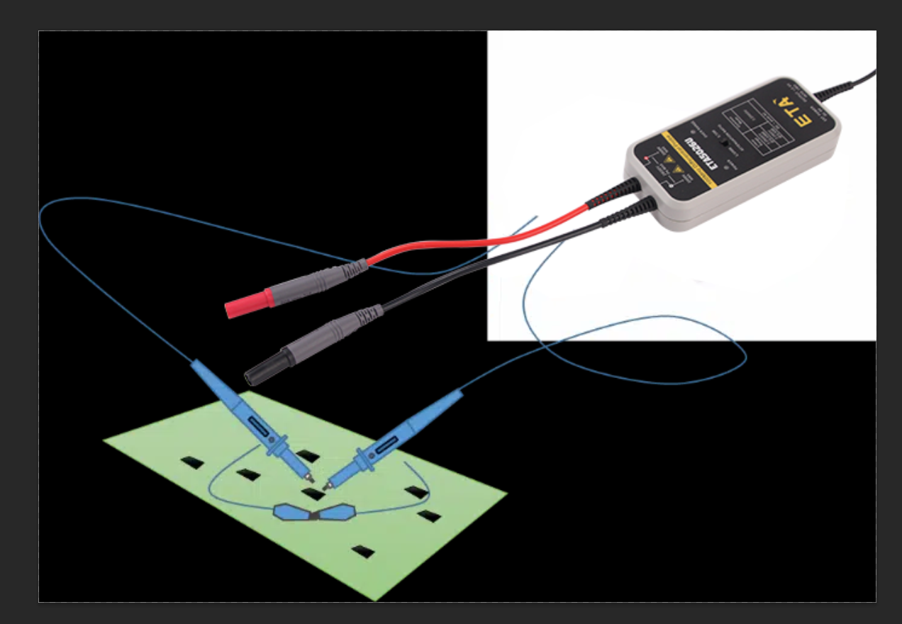
Therefore, for measurement scenarios that require high accuracy and high security, a more elegant solution is to use an active differential voltage probe. This probe has the advantages of true differential measurement, high CMRR and only one oscilloscope channel per measurement. It can effectively solve the measurement problem of floating voltage and differential voltage, and improve the accuracy and safety of measurement.


Building 9, No. 269, Xinfeng Road, Xukou Town, Wuzhong District, Suzhou, China
0512-66559708

WeChat customer

Tmall Official Flagship Store
Copyright © 2003-2025 , All Rights Reserved AiYong Instruments (Suzhou) Co., Ltd.