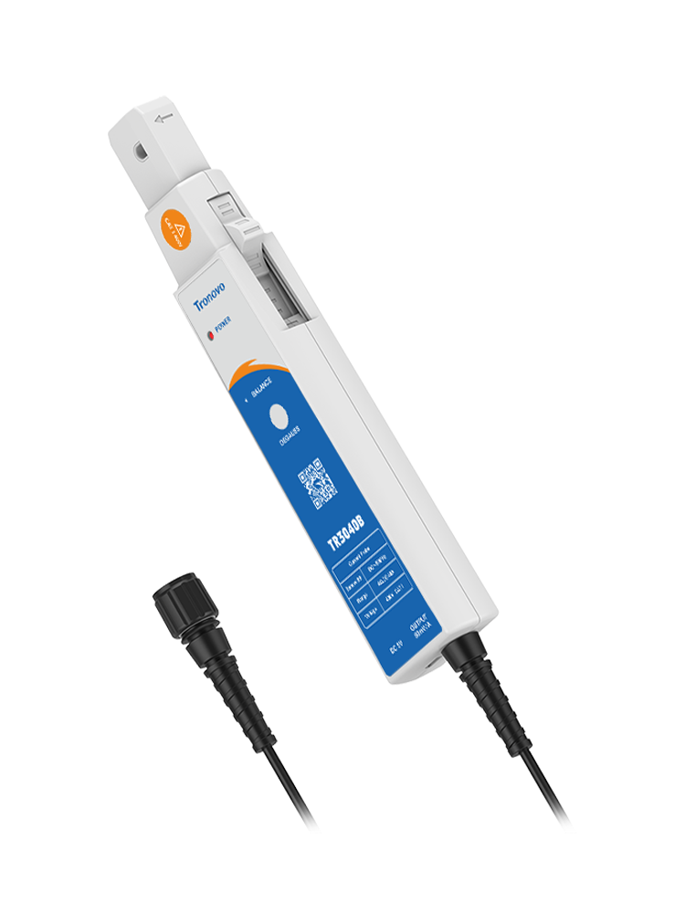
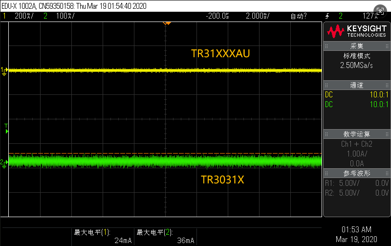
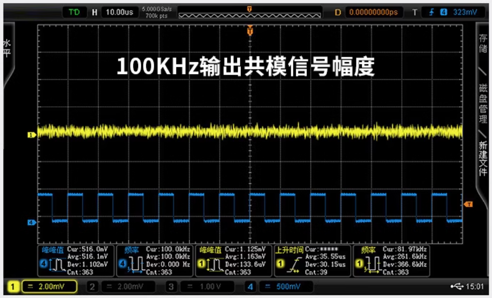
The attenuation ratio of the current probe is like a "translator" and a "zoom mirror" connecting the real current world to the oscilloscope screen ". It defines the scale at which the probe "scales down" the primary current to the output voltage, typically nominally "X mA / Y mV" (e. g., 100 mA/V). This means that for every 100mA current induced, the probe will output 1V voltage to the oscilloscope.
This "zoom mirror" directly determines the life and death accuracy of the measurement. If the wrong attenuation ratio is selected, the small current measurement will be overwhelmed by the background noise, and the large current will force the signal clipping distortion, resulting in complete data failure. More importantly, you must select a gear in the oscilloscope channel settings that is consistent with the probe's physical attenuation ratio. Once the mismatch is set, such as the probe is 100mA/V and the oscilloscope is mistakenly set to 1X, it will introduce up to a hundred times the measurement error, making the result meaningless.
Therefore, the correct understanding and setting of the attenuation ratio is not an optional step, but the cornerstone to ensure that every current measurement is accurate and reliable. It reminds us that precision often begins in awe of the underlying parameters.
