
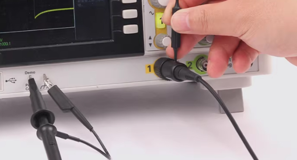
1.1 check whether the probe compensation is in place
When changing the probe channel or using a new probe, if you skip the "probe compensation calibration", it is easy to cause waveform distortion.
Troubleshooting and resolution: Connect the probe to the CAL calibration end of the oscilloscope, switch to the corresponding channel, and set the appropriate time base and voltage gear to ensure stable waveform triggering. Use a non-sensitive screwdriver to adjust the probe compensation capacitance until a standard square wave (clear square corners, no overshoot/undershoot) is displayed.

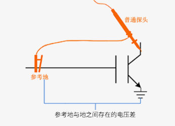
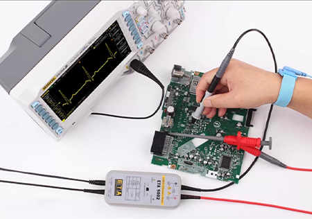
1.2 check whether the grounding is reliable
Improper grounding will introduce interference, especially in high-frequency measurement, 15-30cm long grounding wire is easy to form a large grounding loop, resulting in waveform jitter and clutter.
Investigation and solution: give priority to using ≤ 10cm short grounding wire or grounding spring (high frequency is preferred) to shorten the grounding circuit; The grounding point selects the "signal ground" or "chassis ground" of the circuit under test to avoid parallel laying of probe cables and strong current wires to reduce interference coupling.

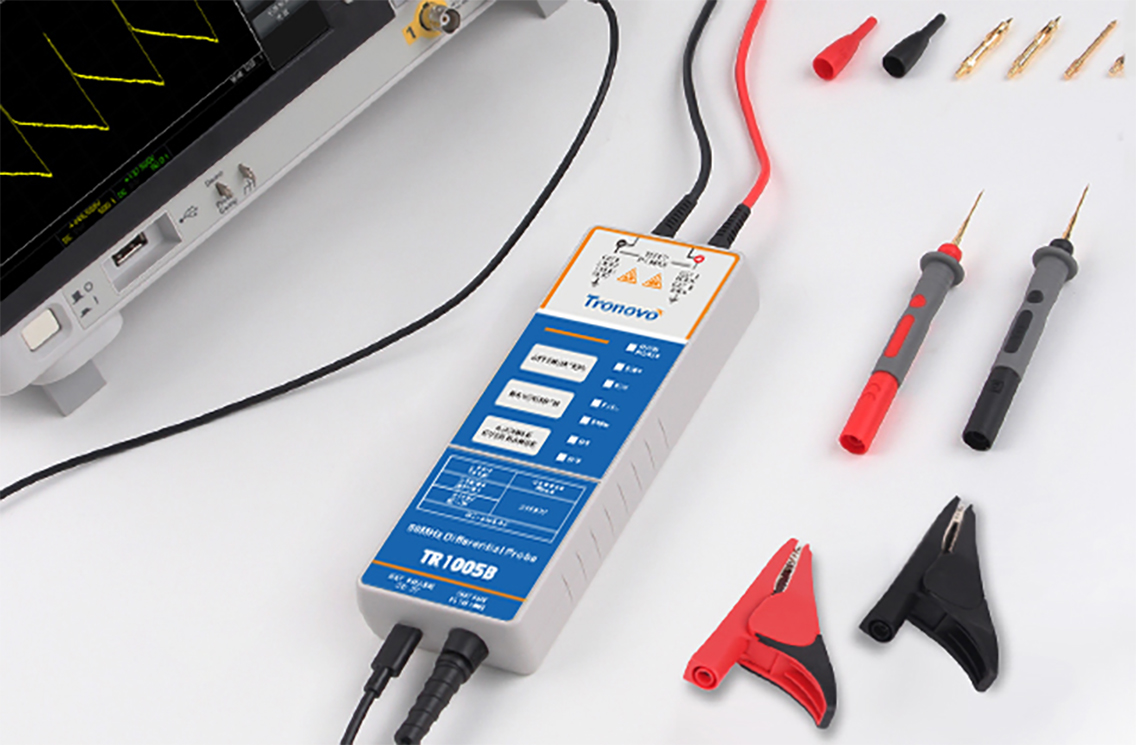
1.3 confirm that the probe bandwidth matches the signal frequency
If the probe compensation and grounding are normal and still distorted, the high probability is that the probe bandwidth is insufficient, resulting in high-frequency signal attenuation.
Investigation and solution: first confirm the frequency of the measured signal, and then check the probe bandwidth parameters-the probe bandwidth should be ≥ 1.5 times (preferably 2 times) of the frequency of the measured signal to ensure that the high frequency components are not attenuated.

Building 9, No. 269, Xinfeng Road, Xukou Town, Wuzhong District, Suzhou, China
0512-66559708

WeChat customer

Tmall Official Flagship Store
Copyright © 2003-2026 , All Rights Reserved AiYong Instruments (Suzhou) Co., Ltd.