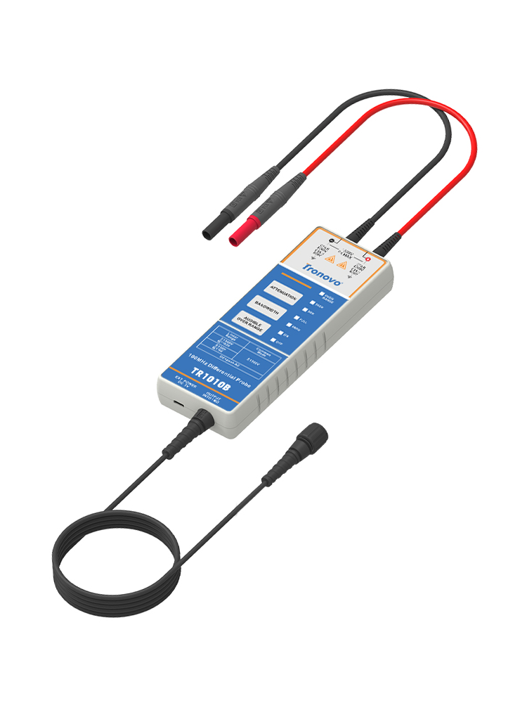

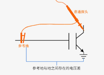
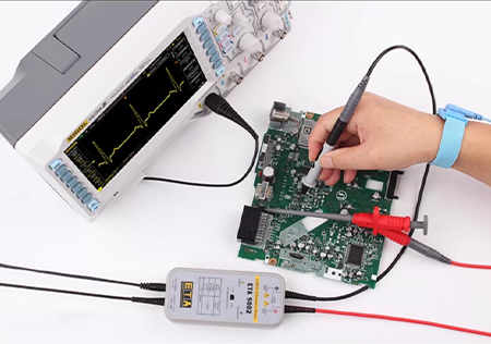
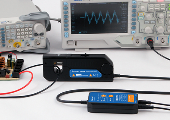
Differential signals transmit information using a pair of voltages (V⁺ and V⁻) with equal magnitudes but opposite phases. As specialized measurement devices, differential probes capture such signals through two mutually isolated floating-ground input channels, converting them into single-ended signals processable by oscilloscopes. Their key function lies in accurately extracting the potential difference between two test points while effectively suppressing common-mode noise interference.
The probe's operational mechanism relies on a differential amplifier structure. It calculates the difference between the two input voltages (Vdiff = V⁺ - V⁻) while suppressing the common-mode component (Vcm = (V⁺ + V⁻)/2), thereby reconstructing the target differential signal in complex noise environments. With its excellent common-mode rejection ratio (CMRR), the differential probe enables safe measurement of floating ground systems, avoiding short-circuit issues that may arise from grounding standard probes.
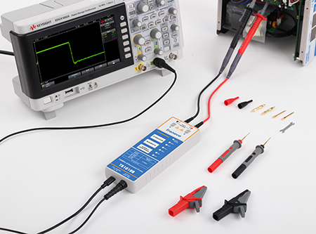
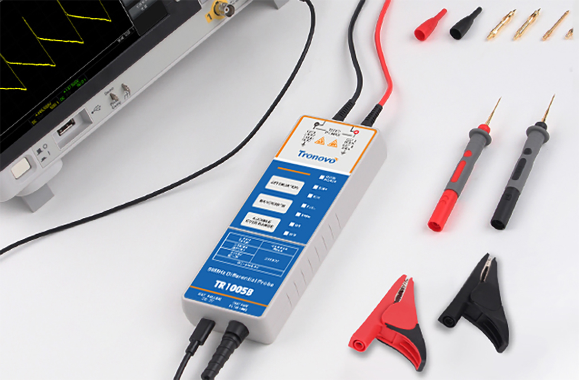
Differential probe technology offers three core advantages: robust noise immunity, safe electrical isolation, and exceptional measurement accuracy. Key performance parameters include bandwidth, common-mode voltage range, differential voltage range, and attenuation ratio. Typical applications encompass switching power supply waveform observation, motor drive system testing, high-speed digital bus signal debugging, and industrial field communication protocol analysis.
During actual selection, prioritize bandwidth matching (recommended at 3 to 5 times the signal's highest frequency) and voltage range applicability. It is crucial to emphasize: never substitute a differential probe with two single-ended probes combined. This practice not only risks short circuits but also causes significant measurement errors due to inconsistent amplitude-phase characteristics between channels. Additionally, always perform DC offset compensation calibration before use to ensure measurement accuracy.

Building 9, No. 269, Xinfeng Road, Xukou Town, Wuzhong District, Suzhou, China
0512-66559708

WeChat customer

Tmall Official Flagship Store
Copyright © 2003-2026 , All Rights Reserved AiYong Instruments (Suzhou) Co., Ltd.