一、Product Overview
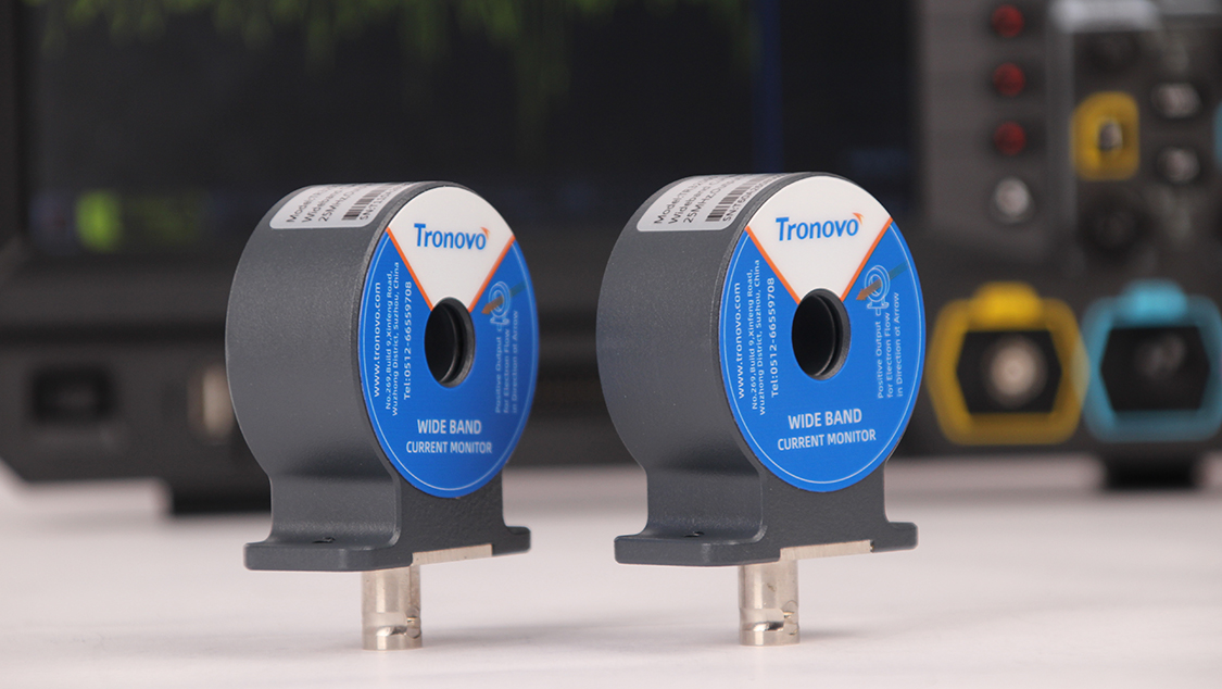
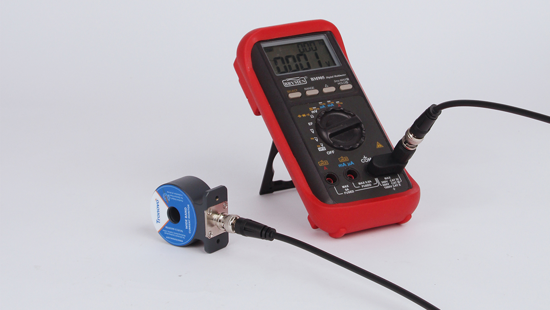
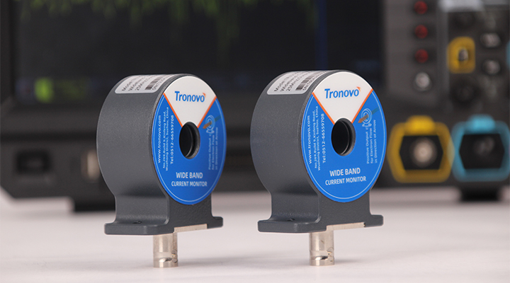
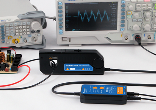
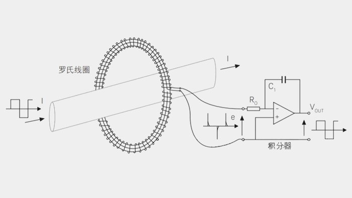
In demanding test scenarios such as power semiconductors, high-frequency switching power supplies, pulsed discharges, and lightning surge testing, accurately capturing rapidly varying AC and pulse current waveforms is of paramount importance. Tronovo TR325110 AC oscilloscope current loop is the 1 high-performance passive through-core current sensor designed for high-frequency and high-current testing. With a response bandwidth of up to 20MHz and exceptional performance capable of handling pulse peak currents of up to 5,000 A, it can safely and distortion‑free convert current signals in high‑frequency, high‑voltage circuits into voltage signals, which are then directly output to an oscilloscope for observation and analysis.
二、Core Competitive Advantages and Key Highlights
1. 20 MHz Broadband response, effortlessly captures transient waveforms.
The maximum frequency response spans 10Hz to 20MHz (–3 dB), faithfully reproducing the current rise edge, spike pulses, and higher-order harmonics during high-frequency switching events while effectively mitigating high-frequency phase shifts and waveform distortion.
2. Strong current measurement capability:100A rms / 5000A pulse peak
Continuous Range: Supports continuous AC current measurement up to 100Arms.
Peak Pulse Current: The transient pulse-handling capability reaches up to 5,000 A peak, easily coping with capacitor discharge, lightning surges (ESD/Surge), IGBT/GaN switching losses, and short-circuit impact tests.
3. 50mA high-sensitivity resolution, balancing the detection of weak signals.
With a minimum resolution as low as 50 mA, it can not only measure high‑pulse currents but also accurately resolve high‑frequency ripple and weak AC components in the circuit’s background.
4. ∅12.7mm Large aperture, high-grade electrical isolation
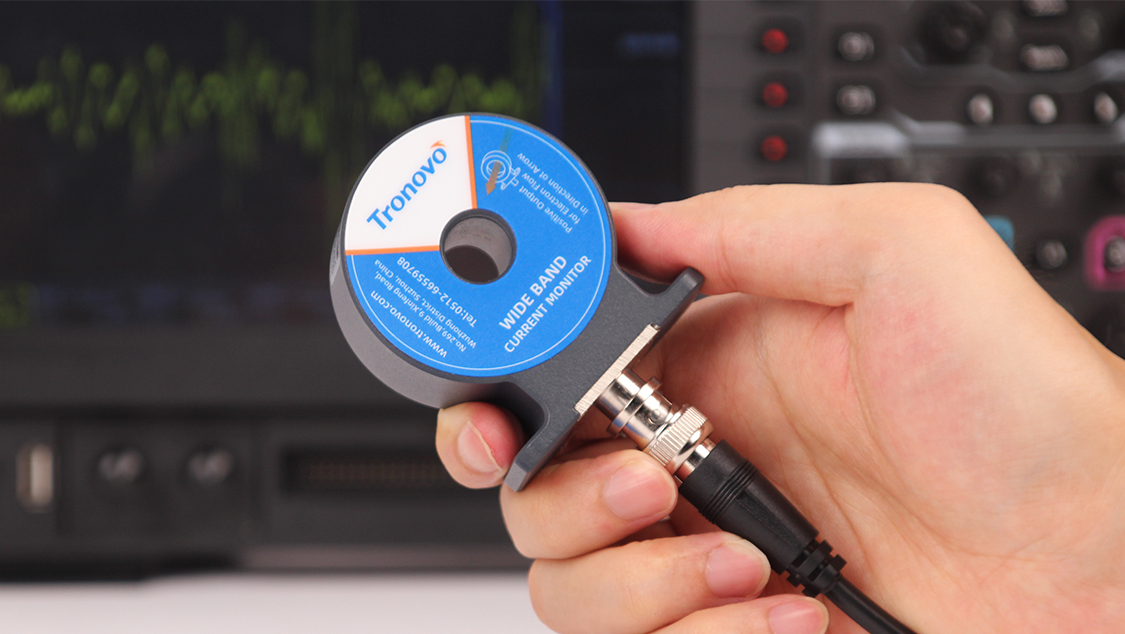
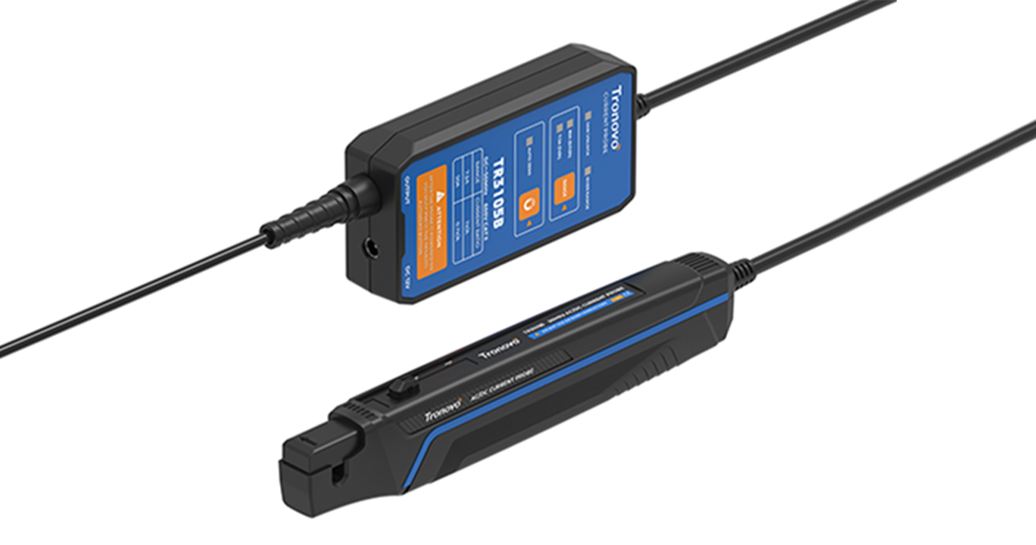
It employs a non-contact, through‑wire design with a through‑hole diameter of ∅12.7 mm, allowing large‑size insulated conductors or high‑voltage cables to be easily passed through. Completely disconnect the direct connection between the measurement circuit and the test instrument to ensure the safety of the oscilloscope and personnel.。
5. Standard BNC connector with intuitive polarity indication
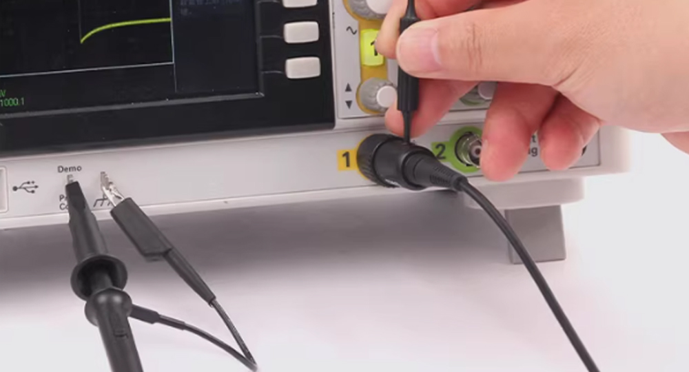
The base is equipped with standard BNC direct‑connect ports, enabling straightforward connection to oscilloscopes from major brands; the body is clearly marked with an arrow indicating the forward direction of current flow, effectively preventing reverse‑polarity wiring errors.
三、 Typical Application Scenarios
Power Semiconductor and Drive Testing: High-frequency switching current and conduction loss testing of wide-bandgap semiconductor devices such as SiC and GaN.
Power Supply and Inverter R&D: Switch-mode power supplies (SMPS), inverters, high-frequency transformers, and inductor current ripple analysis.
Pulse Power and Discharge Systems: Plasma physics research, laser drivers, capacitor discharge, and high-energy pulse measurement.
Electromagnetic Compatibility (EMC/ESD) Testing: Lightning surge impact testing, electrostatic discharge transient current, and conducted interference monitoring.
Industrial Motors and Welding Equipment: High-Frequency Spot Welders, Induction Heating Equipment—Pulsed Current Detection.
四、Precautions for Use
Conductor insulation: The conductor under test must be an insulated wire; do not thread it directly through uninsulated high-voltage bare conductors.
Current direction: Refer to the arrow markings on the current clamp’s surface and thread the conductor through in the indicated direction to ensure the oscilloscope displays the correct waveform polarity.
Impedance Matching: It is recommended to set the oscilloscope’s input impedance to 1 MΩ (or configure a 50-Ω termination as specified in the manual) to achieve the most accurate variable‑scale output.

Building 9, No. 269, Xinfeng Road, Xukou Town, Wuzhong District, Suzhou, China
0512-66559708

Customer after-sales platform

Tmall Official Flagship Store
Copyright © 2003-2026 , All Rights Reserved AiYong Instruments (Suzhou) Co., Ltd.